The Aluminum Die Casting Process, Stage by Stage
Ten defined stages take your CAD file to packed production parts. Each stage has a named output and an owner, so you always know exactly where your program stands.

How an aluminum die casting program runs
The CharMax Precision aluminum die casting process has ten stages: engineering review, DFM analysis, tooling design, mold manufacturing, aluminum die casting, trimming and deflashing, CNC machining, surface finishing, inspection, and packaging. All ten run in our own facility in Dongguan, Guangdong, China.
The first two stages are free and happen before any commitment. Engineering review confirms what you need, and DFM analysis produces a written report identifying the geometry changes that would reduce your cost or your risk. Most of the money in a die casting program is won or lost here, not in the piece price negotiation.
From tooling onwards the process is a controlled sequence with documented outputs: an approved die design, trial-fitted tooling, T1 samples with a dimensional report, an approved first article, then production lots with inspection records. Nothing moves to the next stage until the previous one is signed off.
Process at a glance
| Stages | 10, all in-house |
|---|---|
| Engineering review | Same business day |
| DFM report | 2-3 business days, free |
| Die design | 5-8 days including flow simulation |
| Mold manufacturing | 25-40 days |
| T1 samples | 5-7 days after tooling completion |
| Production lead time | 15-25 days |
| Repeat orders | 15-20 days |
| New program total | 50-75 days to first shipment |
| Quality gate | First article inspection before every release |
From engineering review to packed parts
Every stage below lists what happens, what it produces and how long it takes on a typical program.
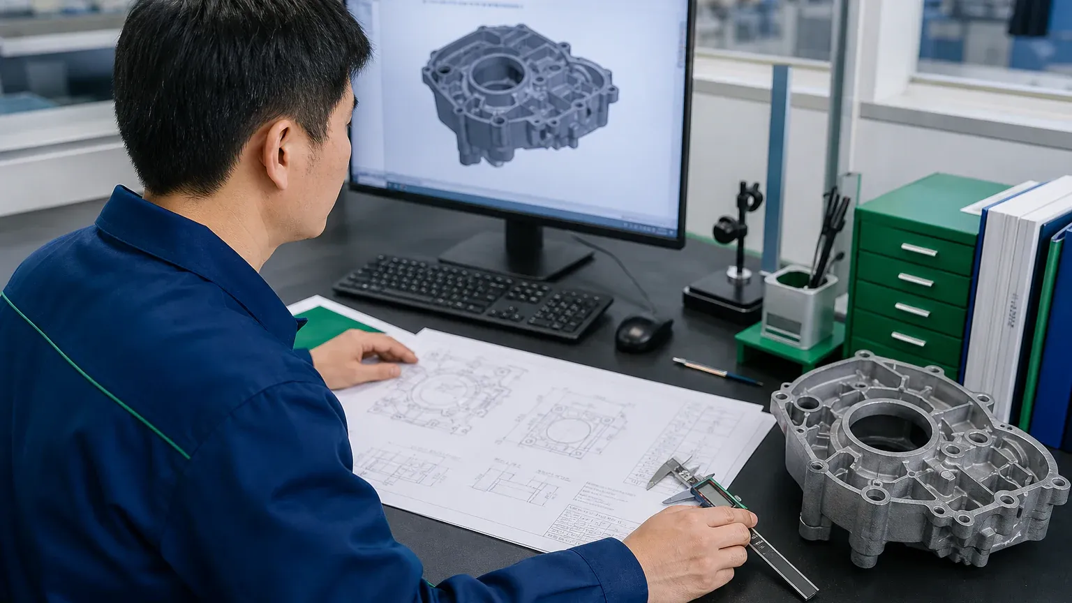
Engineering Review
We open your 2D drawings and 3D models, confirm the alloy, tolerances, finish and annual volume, and flag anything that needs clarification before quoting. You get a single point of contact who is an engineer, not a call centre.
- STEP, IGES, X_T, SLDPRT and PDF drawings accepted
- Volume, target price and target launch date confirmed
- Critical-to-function features identified up front
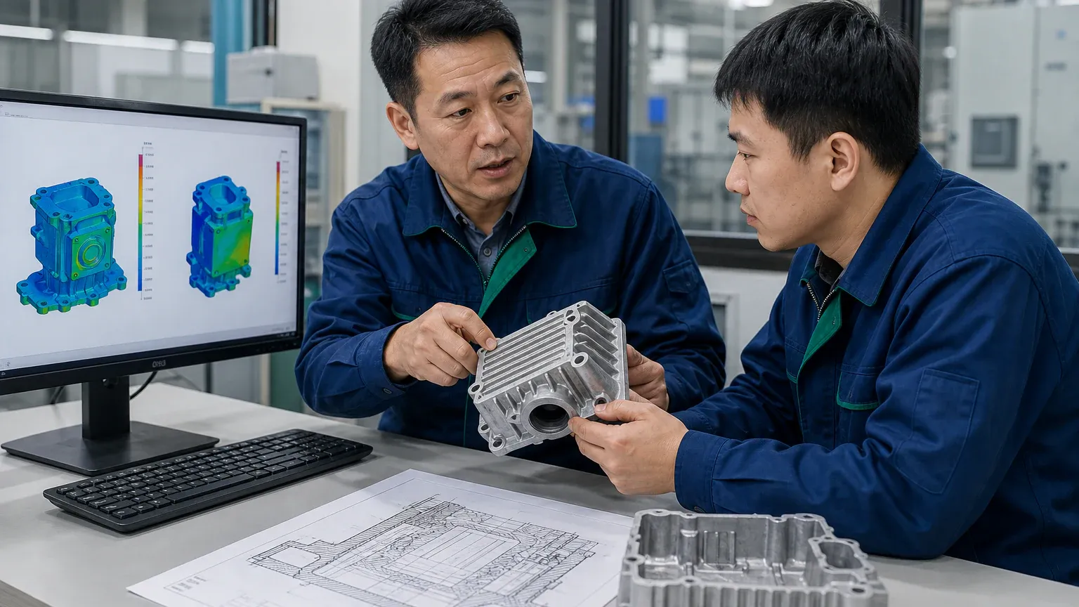
DFM Analysis
Our tooling engineers run a design for manufacturability review and return a written report. We identify wall thickness variation, draft angles, undercuts, parting line placement, ejector locations and features that would be cheaper to machine than to cast.
- Wall thickness and section transition mapping
- Draft angle and parting line proposal
- Machining allowance and datum strategy
- Cost reduction opportunities documented
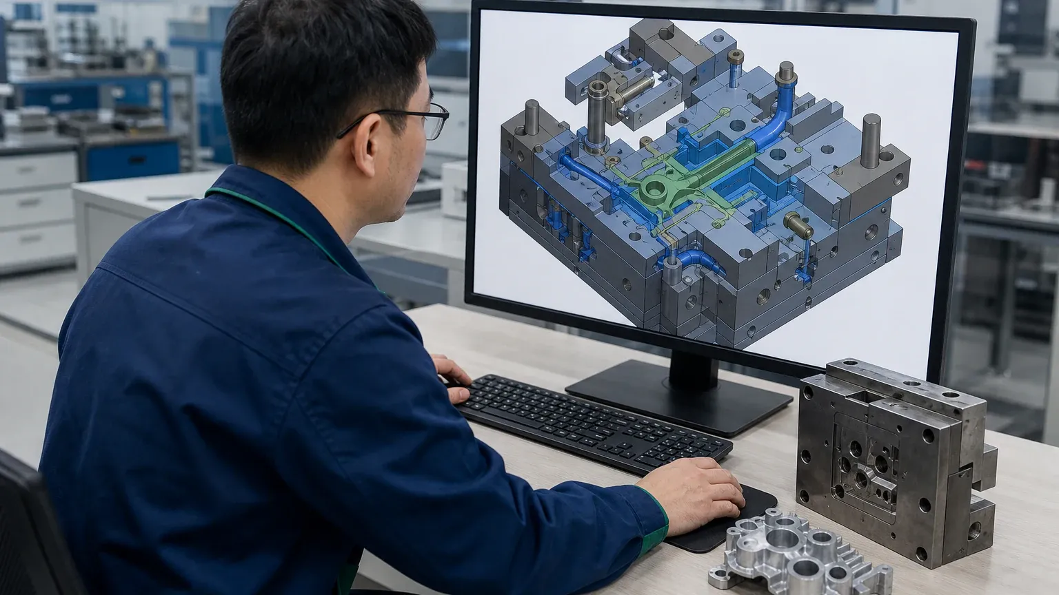
Tooling Design
Once DFM is approved we design the die: cavity layout, runner and gate system, overflow and vent placement, cooling lines, slides and ejector system. Mold flow simulation predicts fill pattern, air entrapment and solidification before any steel is cut.
- Single, multi-cavity or unit die layout
- Gate and overflow system engineered per part
- Mold flow and solidification simulation
- Conformal cooling where thermal balance demands it
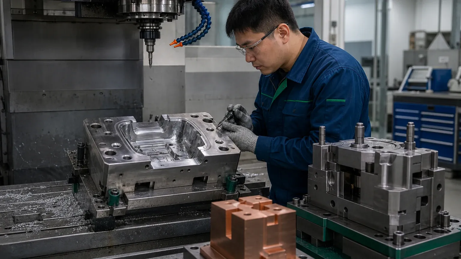
Mold Manufacturing
Dies are cut from H13 hardened tool steel, heat treated to 46-50 HRC, then finished by CNC milling, EDM and grinding. Slides, inserts and ejector systems are fitted and the die is trial fitted before first shot.
- H13 tool steel, heat treated to 46-50 HRC
- CNC, wire EDM and sinker EDM finishing
- Tool life of 80,000-150,000 shots typical
- Spare cores and inserts available on request
Aluminum Die Casting
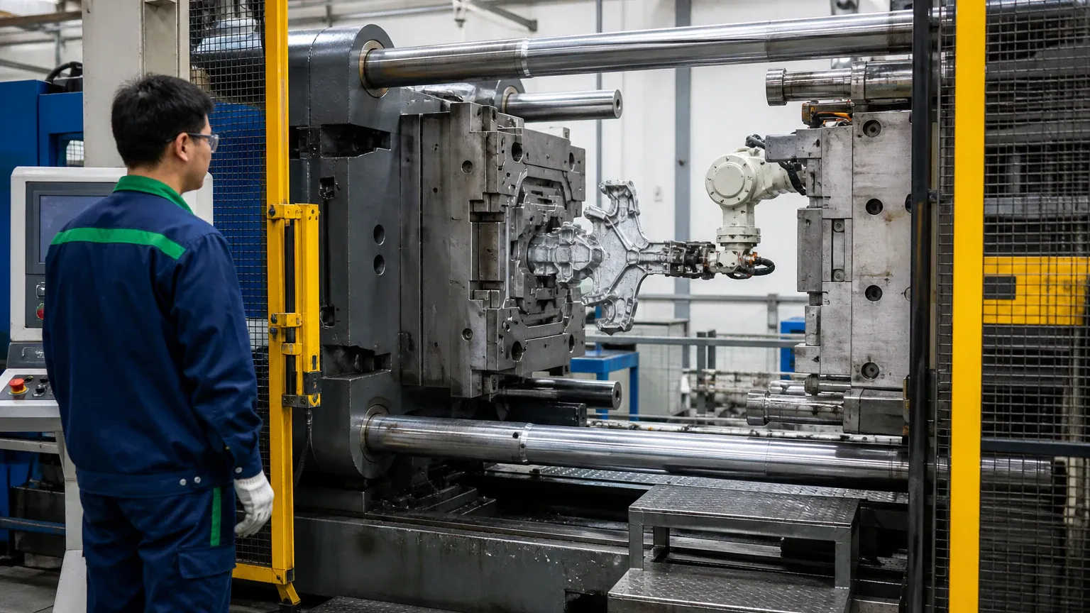
Aluminum is melted and held at 660-700 °C, dosed into the shot sleeve and injected into the die at 40-100 MPa. Cold chamber machines from 160 to 1,250 tons run the part while shot profile, die temperature and cycle time are logged for every batch.
- Cold chamber HPDC, 160-1,250 ton clamping force
- Degassed and filtered melt for reduced porosity
- Die temperature and shot parameters recorded per lot
- T1 sample approval before production release
Trimming and Deflashing
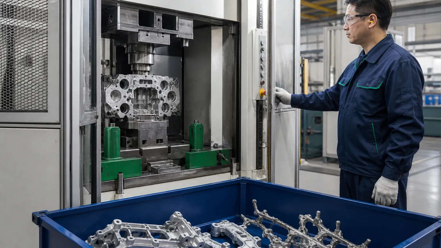
Runners, overflows and flash are removed by trim press, then parts are deburred and shot blasted to a uniform as-cast surface. Gate witness marks are dressed to your drawing requirements.
- Trim die or manual gate removal
- Vibratory and manual deburring
- Shot blasting to Ra 1.6-3.2 µm
CNC Machining
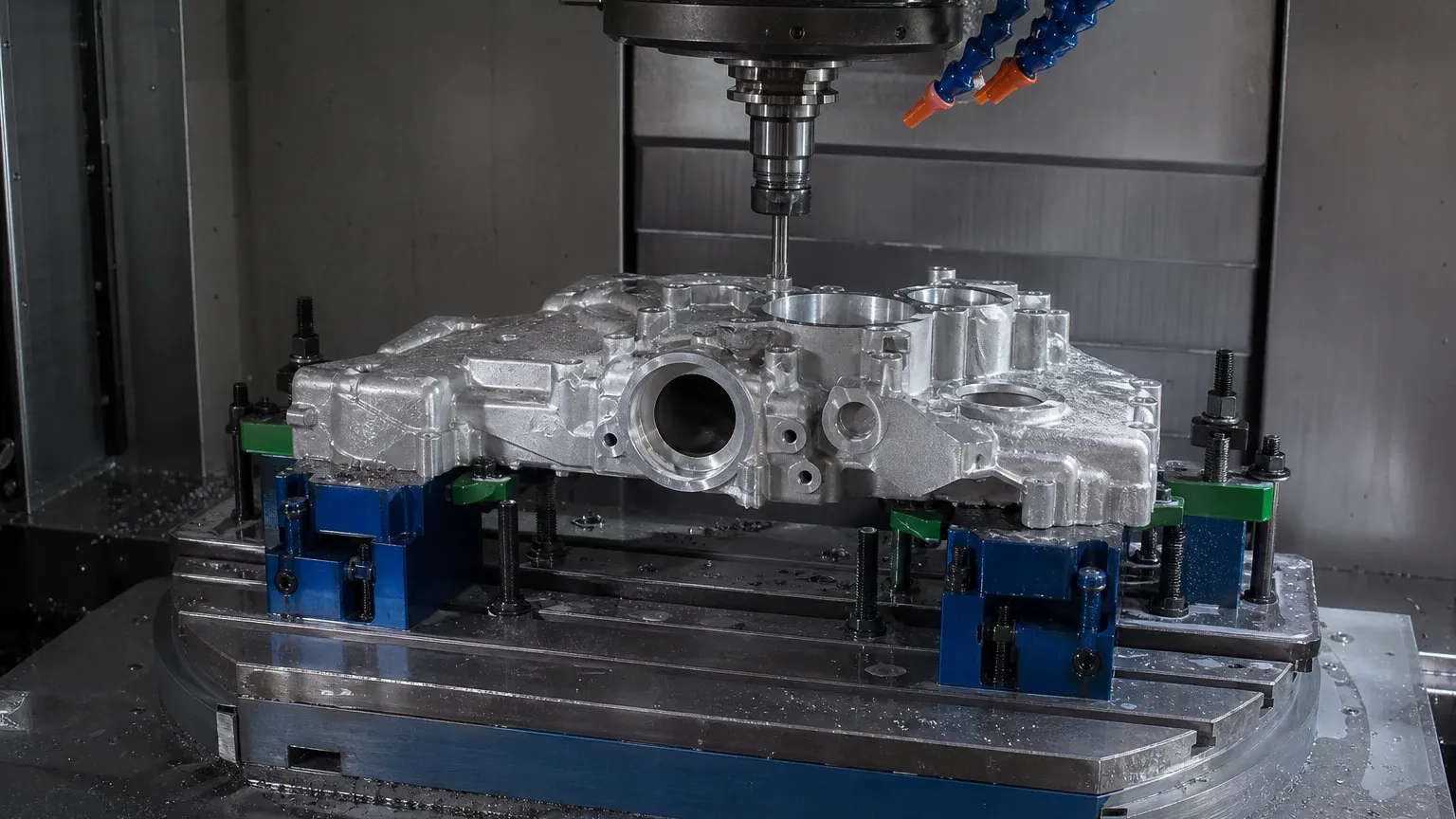
Castings are located in dedicated fixtures and machined on 3, 4 and 5-axis centres to bring sealing faces, bores, threads and datum features to ±0.02 mm. Machining in-house means no inter-factory shipping and one company owning the tolerance stack.
- ±0.02 mm on critical machined features
- Bores, sealing faces, threads and tapped holes
- Purpose-built casting fixtures per part
- Flatness and perpendicularity control
Surface Finishing
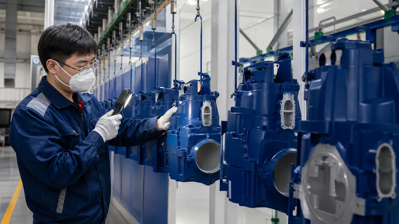
Parts move to the finish specified on your drawing: shot blast, powder coat, wet paint, polishing, chromate conversion or anodizing. Cosmetic parts are inspected against an agreed boundary sample under controlled lighting.
- Powder coating to RAL, Pantone or custom match
- Chromate conversion for corrosion and bonding
- Anodizing on machined and cast surfaces
- Boundary samples for cosmetic acceptance
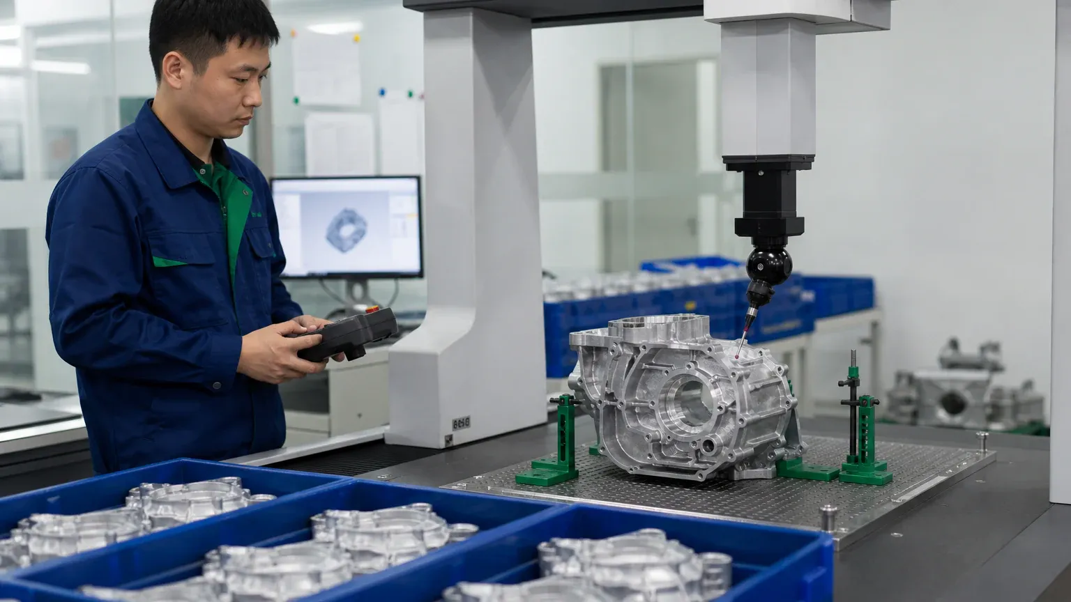
Inspection
First article inspection covers every dimension on the drawing. Production lots are checked to an agreed sampling plan using CMM, height gauges, thread gauges, roughness testers and leak test rigs, with results issued as a dimensional report.
- CMM measurement with dimensional reports
- X-ray or sectioning for internal porosity when specified
- Leak testing for pressure-tight parts
- Material certificates and lot traceability
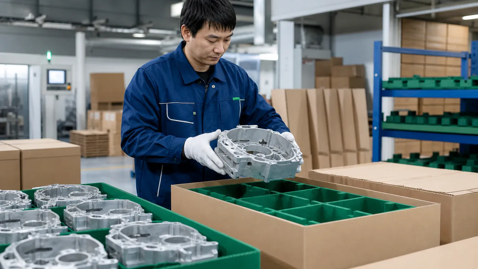
Packaging and Shipping
Parts are packed to protect machined and cosmetic surfaces, labelled to your part numbering, and shipped by sea, air or courier with full documentation. We can ship to your plant, your contract assembler or a third-party warehouse.
- Custom foam, tray, blister or carton packaging
- Barcode and part number labelling to your standard
- Sea, air and express courier options
- Commercial invoice and packing list per shipment


What our DFM review actually checks
Design for manufacturability review is where a die casting program is made cheap or expensive. These are the specific checks we run against your geometry, and the targets we measure them against.
| Check | Target | Why it matters |
|---|---|---|
| Wall thickness | 2-3 mm, uniform | Thick sections trap shrinkage porosity and sink |
| Wall thickness variation | Under 2:1 ratio | Uneven solidification distorts the part |
| Draft angle, external | 1-2° | Insufficient draft drags the surface and wears the die |
| Draft angle, internal | 2-3° | Internal walls shrink onto the core and grip harder |
| Internal radii | ≥1 mm, or 25-50% of wall | Sharp corners heat-check the die and concentrate stress |
| Rib thickness | 60-80% of adjoining wall | Thicker ribs create a thermal mass and sink marks |
| Boss diameter | ≤2× wall thickness at base | Oversized bosses cause localised porosity |
| Parting line | Placed on a non-critical face | Determines which dimensions can hold tight tolerance |
| Undercuts | Eliminated where possible | Each slide adds tooling cost, cycle time and a wear point |
| Machining allowance | 0.5-1.0 mm on machined faces | Too little exposes as-cast surface, too much wastes cycle time |
| Cast datum features | Defined and dimensioned | Fixtures must locate repeatably or machining accuracy varies |
Lead times you can plan a launch around
Work backwards from the date you need parts on your line. The table below is what we commit to on a typical program.
| Stage | Duration | What you receive |
|---|---|---|
| Engineering review | Same business day | Acknowledgement and clarification questions |
| DFM analysis and quotation | 2-3 business days | Written DFM report, piece price, tooling price |
| Die design and simulation | 5-8 days | Die layout drawing and flow simulation summary for approval |
| Mold manufacturing | 25-40 days | Completed die, trial fitted |
| T1 sample casting | 5-7 days | First samples with dimensional report |
| Sample approval | Customer dependent | Your written approval to release production |
| Production run | 15-25 days | Cast, machined, finished and inspected parts |
| Repeat orders | 15-20 days | Production on proven tooling, no sampling stage |
Total time from purchase order to first production shipment is typically 50 to 75 days for a new program. Complex parts with multiple slides or multi-cavity tooling sit at the upper end of each range.
Related capabilities
Services engaged during the process
Alloys we cast
Further reading
Questions about our manufacturing process
How long does the whole process take from order to first parts?
Budget 50 to 75 days from purchase order to first production shipment on a new program. That breaks down as 5 to 8 days for die design and simulation, 25 to 40 days for mold manufacturing, 5 to 7 days for T1 samples, your approval time, and then 15 to 25 days for the production run. Repeat orders on existing tooling ship in 15 to 20 days.
What happens if the T1 samples are out of tolerance?
We measure T1 samples against your drawing and issue a dimensional report before shipping them, so any deviation is identified by us rather than discovered by you. Because our tool room is in-house, most corrections are made in days rather than the weeks it takes when tooling is subcontracted. Die adjustments needed to reach the agreed drawing specification are made at our cost; changes to the design itself are quoted as an engineering change.
Can we visit the factory or audit the process?
Yes. Customers are welcome at our facility in Qingxi Town, Dongguan, and we regularly host quality audits and pre-production reviews. For customers who cannot travel, we run video walkthroughs of the casting cells, machining area and inspection room, and can arrange live video during T1 sampling so you see the first shots as they come off the machine.
Do you provide process documentation and control plans?
Yes. We supply process flow diagrams, control plans, first article inspection reports, dimensional reports per lot and material certificates. For automotive and medical programs we can assemble PPAP-format documentation packages. Tell us which documents your quality system requires at the quotation stage so they are built into the program rather than reconstructed afterwards.
What files do you need to quote?
A 3D model in STEP, IGES, X_T, SLDPRT or native CAD format, plus a 2D drawing showing critical dimensions, tolerances, surface finish, alloy and any inspection requirements. If you only have a 3D model we can still quote, but a drawing that marks which features are critical to function will get you a more accurate price and prevent misunderstandings later.
What is your lead time from purchase order to first parts?
Production tooling takes 25 to 40 days depending on part complexity and cavity count, followed by 5 to 7 days for T1 sample production. After you approve samples, production lead time is 15 to 25 days including machining, finishing and inspection. For repeat orders on existing tooling, expect 15 to 20 days.
How is our intellectual property protected?
We sign your NDA before receiving files and can sign a mutual agreement if you prefer. Your tooling is dedicated to your part and is never used for another customer, your drawings are not shared outside the engineering and production team assigned to your program, and we do not display customer parts or names in marketing material without written permission.
Get a quote on your aluminum die casting part
Send your 2D drawing and 3D model and a manufacturing engineer will review the geometry, confirm the alloy and return pricing with a DFM report. No obligation, no sales scripts.
- Engineering response within 24 hours on business days
- Quotation within 24-48 hours of receiving 2D/3D files
- NDA signed before file review
- Free DFM feedback